whatsapp: 0086-18615575385
E-mail: admin@sdafit.com


1. Scope of Supply:
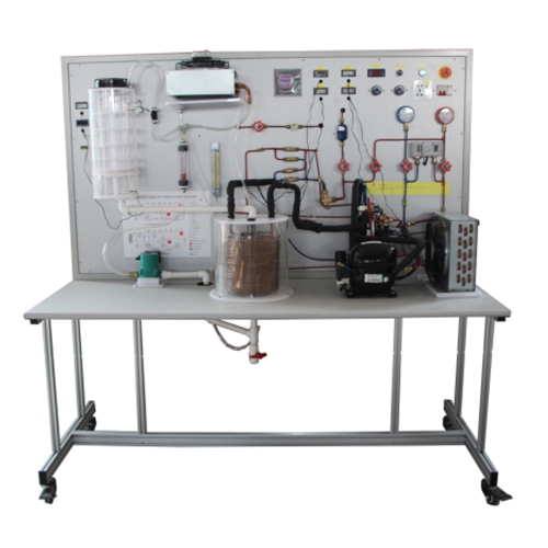
The Contractor shall supply, deliver, install, test, commission, and hand over complete Refrigerator Training System, including:
Training bench with full refrigeration circuit
Integrated data acquisition system
Licensed data acquisition software
RFID power management system
Branded desktop computer
Offline UPS
All instruments, accessories, and documentation.
The system shall be complete, fully operational, and ready for instructional use.
2. General Description:
The Refrigerator Training System shall be a desktop-type educational unit designed for laboratory study of refrigeration thermodynamics and system performance analysis.
The system shall enable students to:
Observe and analyze refrigeration cycle stages
Plot and interpret pressure–enthalpy (P–h) diagrams
Determine superheating and subcooling
Calculate coefficient of performance (COP)
Compare actual cycle performance with inverse Carnot cycle
Evaluate compressor efficiencies
The refrigerant shall be R134a or equivalent environmentally acceptable refrigerant.
3. Mechanical Construction:
3.1 Training Bench:
Movable aluminum profile structure.
Dimensions (Minimum): 1200 (L) × 700 (W) × 1600 (H) mm
Mounted on four (4) castors:
Two (2) with brakes
Two (2) without brakes
Front demonstration board:
Silkscreened refrigeration circuit diagram
Clearly labeled components
Color-coded refrigerant piping (red/blue).
4. Electrical Requirements:
Power Supply: 220V ±10%, Single Phase, 50Hz
Rated Current: 10A (Minimum)
Residual Current Circuit Breaker (16A) (Minimum)
Key switch (self-locking)
Emergency stop button (self-locking)
Overload protector (5A) (Minimum)
Indicator lights (minimum 5 pcs)
Power monitoring module
5. Refrigeration System Components:
The system shall include, but not be limited to, the following:
5.1 Compressor:
Capacity: 1/8 HP (Minimum)
Displacement: approx. 4 cm³
Cooling capacity: approx. 329W (per EN 12900 standard)
5.2 Condenser with Water Tank:
Spiral copper coil (12–14 turns)
Minimum 1/4-inch outer diameter tubing
Submerged in water tank
Heat transfer area approx. 0.082 m²
5.3 Evaporator with Water Tank
Spiral copper coil (7–9 turns)
Minimum 1/4-inch outer diameter tubing
Submerged in water tank
Heat transfer area approx. 0.049 m²
5.4 Circulating Pumps:
Voltage: 220V ±10%
Power: 165W (Minimum)
Adjustable (three power settings)
Flow Rate: Approx. 80 L/min
Quantity: 02 pcs
5.5 Expansion Valve:
Internal balance thermostatic expansion valve (TEV).
5.6 Filter-Dryer:
Minimum 1/4" service connections
5.7 Service and Manual Valves:
Flared thread connection.
Minimum 1/4" pipe diameter.
5.7 Sight Glasses:
Installed on liquid line, suction line, and evaporator inlet (3 pcs).
6. Instrumentation and Sensors:
The system shall include:
Low-pressure gauge: -30 ~ 260 psi
High-pressure gauge: -30 ~ 550 psi
Pressure transmitters: 0–2 MPa (4–20 mA output) – 2 pcs
Temperature transmitters (PT100) – 4 pcs
Digital thermometers (-40°C to +90°C) – 4 pcs
Pointer voltmeter (0–250V)
Pointer ammeter (0–5A)
LCD display for real-time measurement display
Analog input module
Power monitoring module
High/low pressure controller.
Pressure and temperature shall be measurable at multiple points throughout the refrigeration circuit.
7. Water Tank and Heat Exchange System:
Evaporator and condenser coils shall be submerged in separate water tanks.
Water tank temperature sensor shall be provided.
Circulating system shall allow water circulation between tanks during steady-state experiments.
System shall allow demonstration of cooling and heat pump cycles.
8. Integrated Data Acquisition System:
The system shall include a built-in multi-functional data acquisition system with the following minimum specifications:
USB interface connection to computer.
Real-time data acquisition
High-precision measurement capability
Manual and automatic data recording
Configurable sampling intervals (time or interval-based)
Digital and analog instrument display modes
User-friendly graphical interface
Customizable layout and display
All necessary USB cables shall be supplied
9. RFID Power Management System (Mandatory):
The equipment shall include an integrated RFID-based power control system with:
Operating frequency: 13.56 MHz (high frequency)
Communication via RS485 (Standard)
OLED display for RFID card information
Audible status prompts
LED indicators
Data verification capability
Parameter configuration via software
ISO-15693 protocol compliance
Support for ModBus_TCP and ModBus_RTU
The RFID system shall control power activation via card authentication.
10. Additional Equipment:
10.1 Branded Desktop Computer:
Brand: HP, Dell or equivalent approved brand
Manufacturer reference:
Minimum specifications:
Processor: Intel Core i5 (10th Generation or higher)
Cache: Minimum 12MB
Base frequency: 2.5 GHz or higher
RAM: 8GB DDR4
Storage: 1TB SATA HDD or better
Graphics: Integrated
Monitor: 21.5-inch minimum
Resolution: Minimum 1366 × 768
Interfaces: VGA ×1, HDMI ×1
Keyboard and mouse: USB, same brand
Operating system: Free-DOS or equivalent
10.2 Uninterruptible Power Supply (UPS):
Type: Offline UPS
Capacity: Minimum 650VA
Backup time: Minimum 10 minutes at full load.
Support: 1 computer + 1 monitor.
11. Learning Capabilities:
The system shall support the following laboratory exercises:
11.1 Use of pressure–enthalpy charts
11.2Determination of superheat and subcooling.
11.3 Refrigeration energy balance.
11.4Calculation of Coefficient of Performance (COP).
11.5Determination of isentropic and volumetric efficiencies.
11.6nfluence of heat source and sink temperatures on COP.
11.7Comparison between actual cycle and inverse Carnot cycle

 Login
 Inquiry List