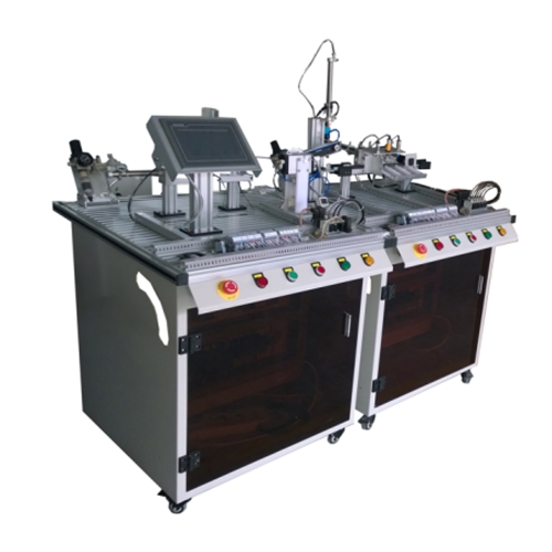
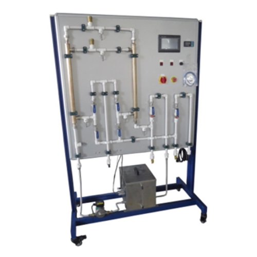
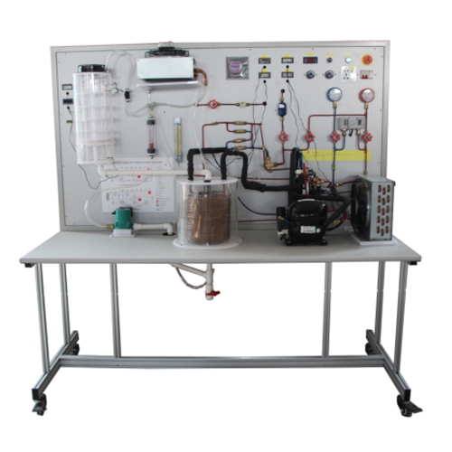
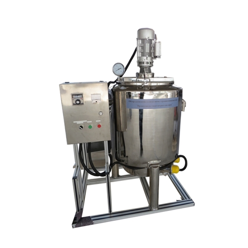
AY261014QA05 Air Conditioner Training System Didactic Equipment School Educational Equipment Air Conditioner Trainer
1. Scope of Supply:
The Contractor shall supply, deliver, install, test, commission, and hand over complete General Air Conditioning Training System, including:
Fully operational air-conditioning and humidity control training unit
Integrated refrigeration system
RS485 data acquisition system
Refrigeration monitoring software
Instrument control panel
Standard accessories and documentation
The equipment shall be factory assembled, fully piped and wired, tested, and ready for immediate laboratory operation.
2. General Description:
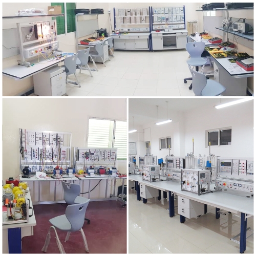
The General Air Conditioning Trainer shall be designed for vocational and technical training in:
Refrigeration cycle operation
Heating, cooling, humidification, and dehumidification processes
Electrical control circuits for refrigeration systems
Refrigeration performance measurement and analysis
Computer-based data acquisition and monitoring
The system shall simulate the complete air-conditioning process including cooling, heating, humidification, and dehumidification stages.
Refrigerant shall be R134a or equivalent environmentally acceptable refrigerant.
3. Mechanical Construction:
3.1 Workbench Structure:
Rigid aluminum profile and steel structure frame
Approximate Minimum dimensions: 1500 (L) × 750 (W) × 1650 (H) mm
Mounted on four (4) heavy-duty casters:
Two (2) with brakes
Two (2) without brakes
Fully installed refrigeration piping and electrical connections
Refrigeration circuit diagram and electrical schematic provided
Refrigeration pipelines color-coded:
Red: High pressure
Blue: Low pressure
3.2 Visibility and Monitoring:
Sight glass installed for refrigerant state observation
Clearly labeled components
Screen-printed panel for instructional reference
4. Electrical Requirements:
Power Supply: Single-phase 220V ±10%, 50Hz
Rated Current: 16A (Minimum)
Leakage circuit breaker 16A (Minimum)
Key switch (self-locking type)
Emergency stop button (self-locking type)
Overload protector 10A (Minimum)
Indicator lights (minimum 5 pcs)
DC Power Supply:
o Output voltage: 24V
oOutput current: 3A.
5. Refrigeration and Air Treatment Components:
The system shall include, at minimum:
5.1 Sealed Compressor:
Power: 1 HP
Voltage: 220V ±10%, Single-phase
Refrigerant: R134a or equivalent
5.2 Condenser (with Fan):
Power Supply: 220V AC ±10%
5.3 Evaporator (with Fan):
Power Supply: 220V ±10%
5.4 Humidification Units:
Primary Humidifier:
Dimensions: approx. 300 × 260 × 300 mm
Capacity: 2.3 liters
Secondary Humidifier:
Capacity: 1 liter
5.5 Heater
Single-phase 220V ±10%
5.6 Solenoid Valve:
220V ±10%
Welded connection
5.7 Manual Valves:
Flared thread connection
Pipe diameter: Φ6 mm (Minimum)
Quantity: 3 pcs
6. Instrumentation and Control:
The system shall include:
6.1 Pressure Measurement:
High-Pressure Gauge:
Range: 0–3.8 MPa
Flared thread connection
Low-Pressure Gauge:
Range: 0–1.8 MPa
High- and low-pressure controllers
Pressure Transducer Sensors:
Range: 0–2 MPa
Output: 4–20 mA (2 pcs)
6.2 Temperature Measurement:
Digital Temperature Displays (4 pcs):
Range: -50°C to +110°C
Accuracy: ±0.5°C
Resolution: 0.1°C
NTC thermistor with protective sheath
Temperature Controller:
Heating output: AC220V
Cooling output: AC220V
Humidification output: AC220V
6.3 Electrical Monitoring:
Pointer voltmeter: 0–250V
Pointer ammeter: 0–10A
Power monitoring module (24V supply)
Analog input module (24V supply)
Fan speed governor:
Input: 220V
Output: 10–220V adjustable
7. RS485 or Standard Data Acquisition System:
The system shall include an integrated RS485 or Standard data acquisition system enabling communication between the refrigeration system and a computer.
The system shall transmit the following parameters to the computer:
Voltage
Current
Phase angle
Frequency
Power
High and low pressure
Time
The system schematic diagram shall be viewable on the computer interface.
The system shall allow data logging and printing via computer terminal.
8. Refrigeration Monitoring Software:
The supply shall include licensed Refrigeration Monitoring Software, capable of:
Real-time system parameter display
Data recording and storage
Graphical system diagram display
Printing of recorded data
RS485 communication integration
Software shall be compatible with standard Windows-based PC systems.
9. Functional Capabilities:
The system shall enable the following laboratory exercises:
Identification and study of air-conditioning system components
Observation of refrigerant states in the compression cycle
Study of heating, cooling, humidification, and dehumidification processes
Determination of:
Refrigeration effect
Work input
Actual and theoretical cycle power
Relative cycle power
Refrigeration capacity
Equipment efficiency
Computer-based data acquisition and analysis



 Login
 Inquiry List